Post 04 - Power Plant Equipments and its Functions
FUNCTIONAL DESCRIPTION
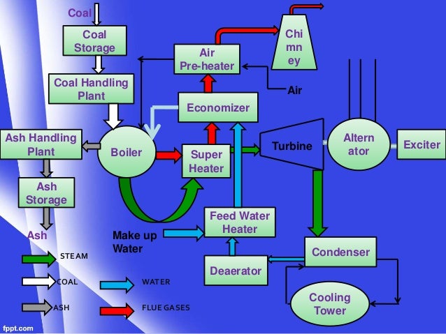
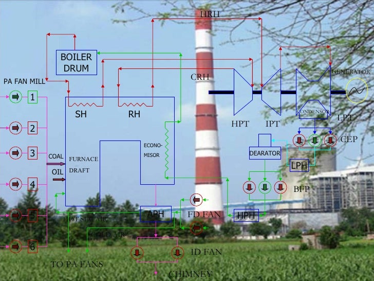
Power Plant

In
Thermal Power Station fuel burns & use the resultant to make the steam,
which derives the turbo generator. The Fuel i.e. coal is burnt in pulverized
from. The pressure energy of the steam produce is converted into mechanical
energy with the help of turbine. The mechanical energy is fed to the generator
where the magnet rotate inside a set of stator winding & thus electricity
is produced in India 65% of total power is generated by thermal power stations.
To understand the working of the Thermal Power Station plant, we can divide the
whole process into following parts.
1. COAL
FLOW
In
coal fired plants, raw material are air & water in PTPS, coal is
transported through Railway wagons from M/s Coal India & is kept reserved
on a buffer stock. The brought out to the station is unloaded with the help of
wagon tippler. After unloading, the coal is sent to crusher house with the help
of conveyor belts. The coal which is now reduced to very small pieces is sent
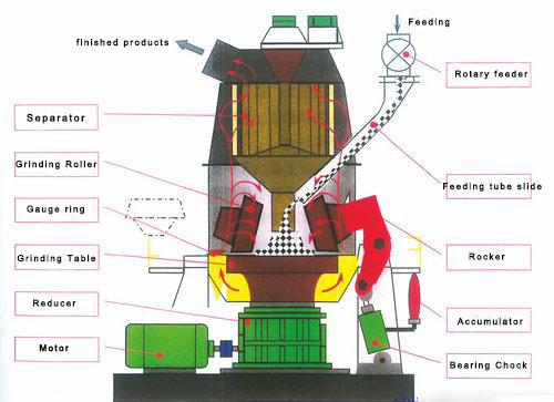
to the coal bunkers with the help of conveyor belt. The raw coal is fed to coal mills through raw
coal feeders raw coal feeders basically regulate raw coal to pulverized coal
pipes. A position of the primary air is heated utilizing the heat of the fuel
gases & then mixed with the cold air as per requirement by the pulverized
coal. Normally the temperature is maintained at 60 to 70 degrees. The coal is
now burnt in the furnace using oil in the beginning showered through the
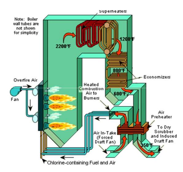
nozzles at different elevations in the furnace. To provide air for combustion,
the heat of the flue gases also heat it the heat produced due to combustion is
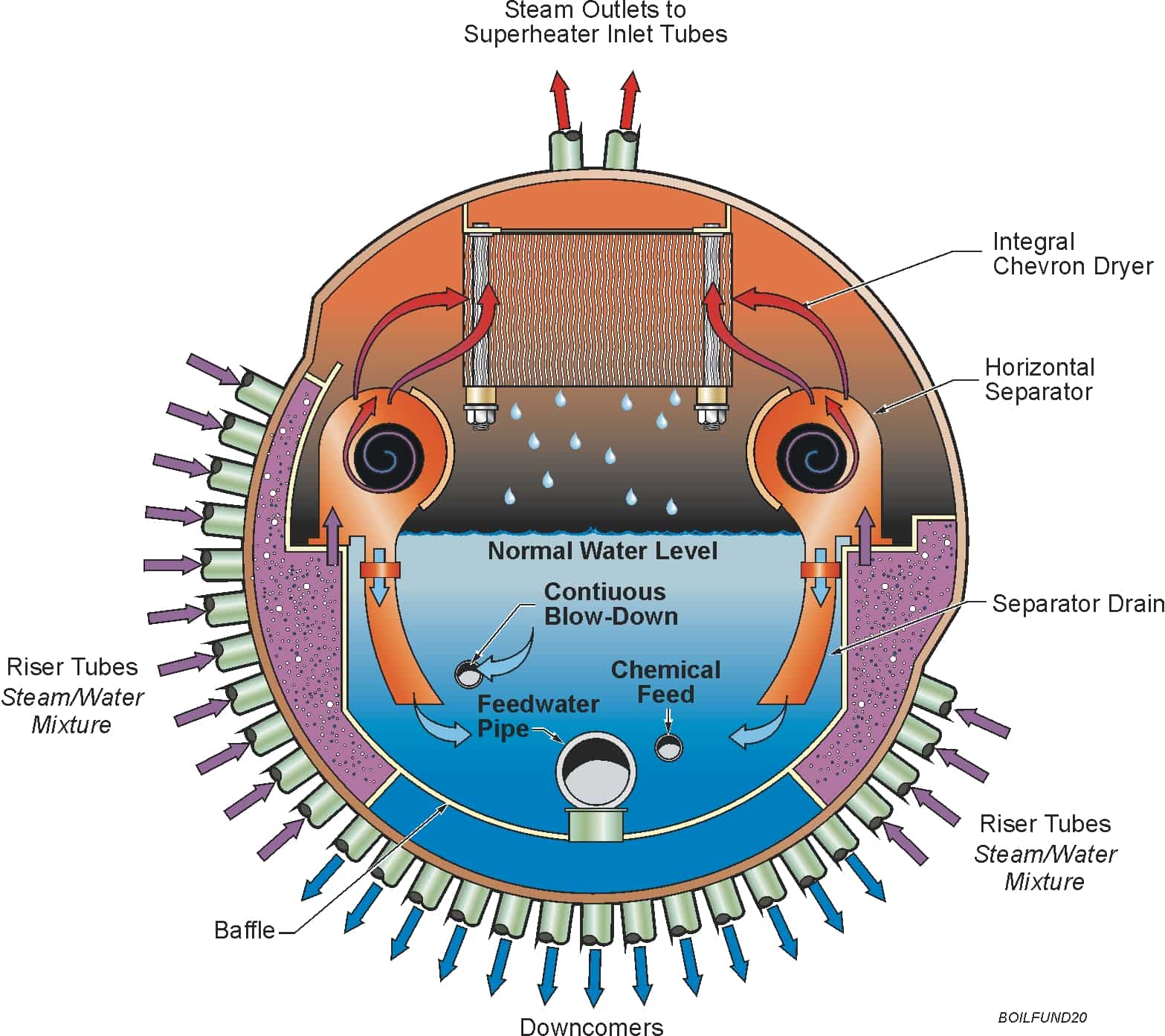
utilized for the conversion of water into steam. This water is stored in the
boiler drum. There are two sets of pipes attached to the drum, one called riser
& other known as down corner through which the water comes to the ring
header & steam moves up due to the density difference of water & steam.
Its steam is super heated using super heaters & meanwhile the flue gases
are through out in the atmosphere through chimney.


2. STEAM FLOW
The
super heated steam is sent to the turbine through pipelines there are three
turbines in the units, using this steam at different temperature &
pressures. After passing through high pressure turbine the steam is send to the
reheater for risingthe temperature of the steam. After reheating the steam is
sent to the intermediate pressure turbine through reheated line. Here it losses
most of its temperature & pressure & finally sent to low pressure
turbine. The uses of three different turbines help in increasing the efficiency
of the plant. The turbine in turn connecting with a generator produces
electricity. Then this electricity is stepped up to grid voltage with the help of step
up transformer & supplied to various sub-stations grids.
Meanwhile,
the steam through low pressure (L.P.) Turbine is condensed and the condensed
water is stored in hot well.

3. WATER FLOW
The
condensed water is extracted from the hot well through condensate extraction
pumps & sent to the boiler drum with the help of BOILER FEED PUMP (B.F.P.)
before passing through low pressure heater and dearater. While loss in water is
make up from C.S. Tank, which have D.M. Moor in it. The C.S. Tank is directly
connected to hot well.
The
water used in condenser is sent to cooling tower for cooling. After cooling
this water is again sent to condenser with the help of circulating water pump.
The loss is making from raw water pump house through clarifier pump house.
 |
| RO PLANT |
COMPONENTS
DESCRIPTION
1. WAGON TIPPLER:
It
is the machine which is used to tip the coal from the wagon. The coal tipped is
directly feed to conveyor belt. Its capacity is 12 wagon per hour.

2. CRUSHER:
It crushes the coal
into small pieces.


3. COAL MILLS:
In
it small pieces of coal are converted into pulverized from. They are 6 in
number.

4. FURNACE:
It is the chamber in
which fuel burns & fire blows.

5. BOILER DRUM:
It contains water for
boiling.

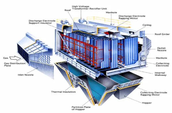
6. ELECTROSTATIC PRECIPITATOR:
In
this we have electrodes which attract fly ash and extract it from flue gases so
that it cannot enter atmosphere.
7. CHIMENY:
It is used to release
flue gases into the atmosphere.
8. TURBINE:
Turbine
is the part which revolves due to steam pressure. It is of three types.
a) High
pressure turbine.
b) Intermediate
pressure turbine.
c) Low
pressure turbine.

9. TURBO GENERATOR:
It
is the main machine which produces electricity .It is (H2O)
water and H2 (Hydrogen) gas cooled therefore it is contained in
cylindrical chamber.


10. CONDENSER:
It condenses steam coming from low pressure turbine (L.P.T.)
to hot water. By removing air and other non-condensable gases from steam while
passing through them.


11. COOLING WATER (C.W.) PUMP:
This pump send water
from cooling tower to condenser.

12. COOLING TOWER:
It
is used to coal the water its height is near about 143.5 mtrs. The hot water is
led to the tower top and falls down through the tower and is broken into small
particles while passing over the baffing devices. Air enters the tower from the bottom and flow
upwards. The air vaporizes a small percentage of water, thereby cooling water
falls down into tank below the tower from where it is pumped to the condenser
and cycle is repeated.


13. RAW WATER PUMP HOUSE:
It supplies raw water
to the boiler.

14. CLARIFIER PUMP HOUSE:
The
water from raw is clear at clarifier by putting alum in it & filtering it
& then supplied to the condenser.


15. CONDENSATE EXTRACTION PUMP:
C.E.P.
pump is used to extract the condense water from the hot well and supply to the
deaerator after passing through L.P. heater & Economizer, so that high
pressure steam in the cylinder can be created.


16. LOW PRESSURE HEATER:
It
is used to increase the temperature of water, in this way efficiency of system
increases.

17. DEAREATER:
It
is used to remove air from water which is entrapped in the water molecules. It
is very important part because the entrapped air effect air drum badly.

18. BOILER FEED PUM (B.F.P.):
It
is the heaviest drive in the plant & supply water to boiler drum from dearator.

19. HIGH PRESSURE HEATER (H.P.):
In
this temperature of water increases. Thus efficiency further increases.

20. ECONOMISER:
In
this flue gases exchange heat to the water to increase system efficiency, causes saving in fuel consumption
(5 to 10%). Economizer tubes are made up of steel either smooth or covered with
fins to increase the heat transfer surface area.


Comments
Post a Comment